MECHANISMS FOR TRAVERSALS
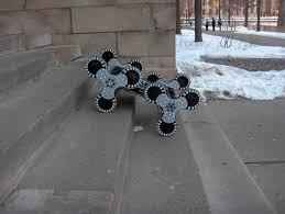
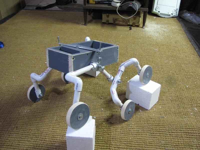
MECHANISM 1 : Four Legged Mechanism
Design:
This mechanism consists of a robot having four “tri-lobe legs”, each leg having a wheel with three lobe-like attachments at 120-degree angle to each other.
Material required:
-
Basic rectangular chassis
-
Four tri-lobe wheels
-
Four DC Motors
-
Wires
-
Skid-Steer Drive
Steps of construction:
-
Make the Wheel Template
-
Cut-out the wheels, and drill a hole in the middle
-
Join the wheels to the chassis with connecting axles
-
Join the motors to the wheels
-
Make connections of your motor to the circuit of Skid-Steer Drive.
-
Your robot is ready to work.
Working:
-
The bot approaches the stair
-
One lobe of each wheel lands on the stair
-
For the wheel to move, the lobes of the front wheels push down on the upper stair while the lobes of the back wheels push down on the lower stair
-
The chassis is lifted in the air, and moves ahead until the next lobe lands on the next stair.
-
The trilobed wheels have usual functioning for traversal on level surface.
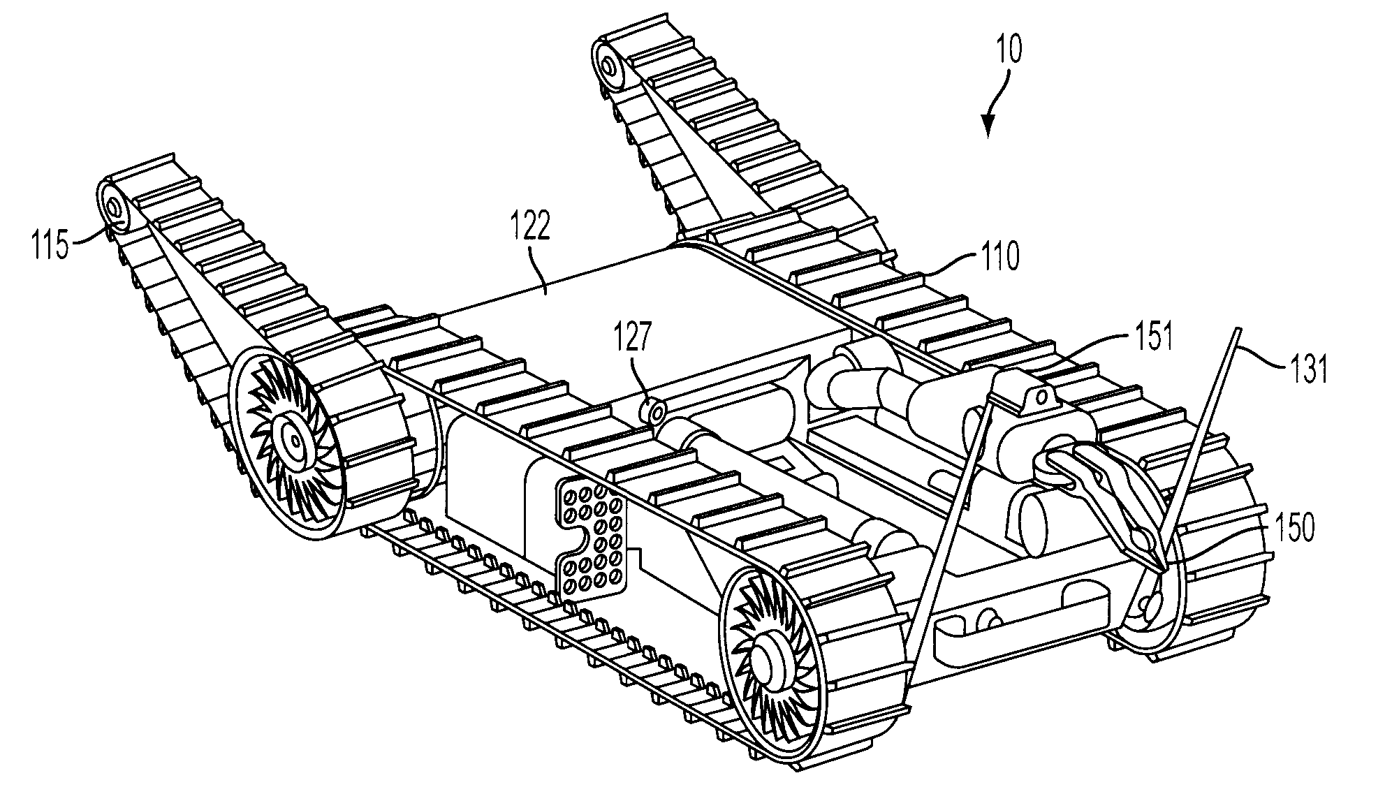
MECHANISM 2 : Conveyor Belt Mechanism
Design:
The conveyor belt mechanism consists of a robot attached with two conveyor belts- an inclined secondary belt in the front and a horizontal primary belt below the bot.
Material required:
-
Basic rectangular chassis
-
Four conveyor belts-two long, two short
-
Six wheels
-
Two rollers(small)
-
Four DC Motors
-
Three connecting axles
-
Wires
Steps of construction:
-
Attach four wheels to the diagonally opposite corners of the chassis
-
Attach the conveyor belt on the wheels
-
Connect one wheel each to the outer side of front wheel by an axle.
-
Connect the two small rollers to each other and the bot at an elevated angle.
-
Attach the second conveyor belt as shown.
-
Attach all the motors to the four inner wheels.
-
Make all the corresponding connections for running the motors
Working:
-
When the bot approaches the stair, the secondary conveyor belt gets in contact.
-
It pulls the bot forward until the front half leaves the ground and the primary belt gets in contact with the stair.
-
The primary belt moves, pulling the whole chassis up.
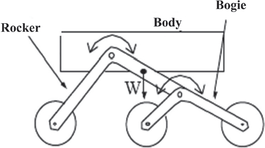
MECHANISM 3: Rocker Bogie Mechanism
Design:
The Rocker-Bogie design has no springs and stub axles for each wheel, allowing the rover to climb over obstacles, such as rocks, that are up to twice the wheel’s diameter in size while keeping all six wheels on the ground.
In order to go over a vertical obstacle face, the front wheels are forced against the obstacle by the center and rear wheels. The rotation of the front wheel then lifts the front of the vehicle up and over the obstacle. The middle wheel is then pressed against the obstacle by the rear wheels and pulled against the obstacle by the front until it is lifted up and over. Finally, the rear wheel is pulled over the obstacle by the front two wheels. During each wheel’s traversal of the obstacle, forward progress of the vehicle is slowed or completely halted
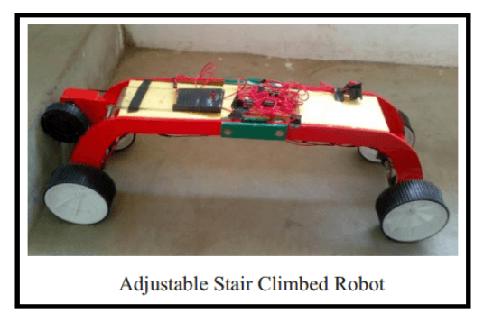
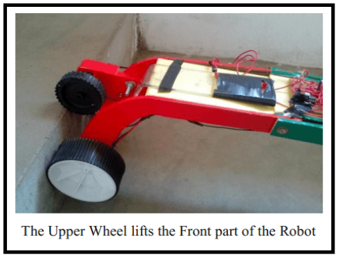
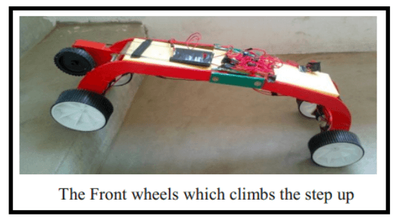
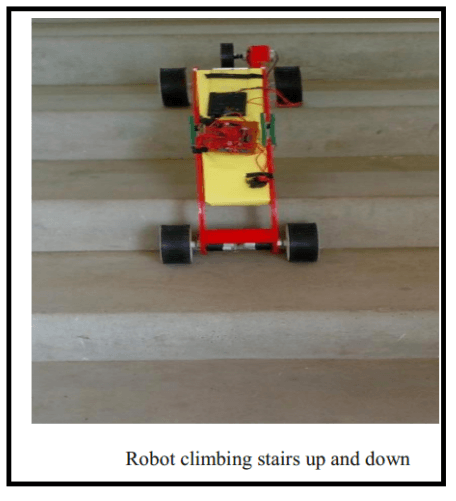
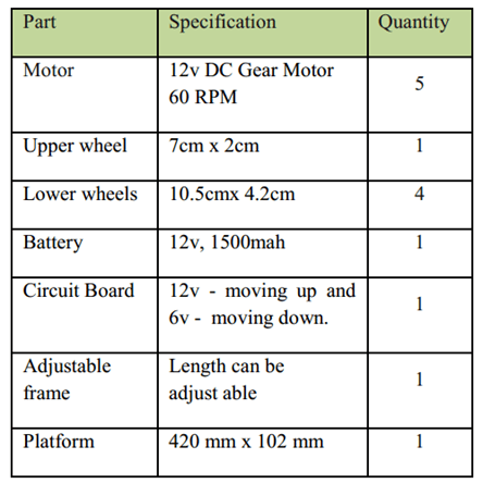
MECHANISM 4: Adjustable Robot Mechanism
Design:
The design and mechanism of the robot is simple as shown below :-
Material required :
Steps of construction:
-
Prepare the chasis as shown in figure.
-
Make the connections of the four motors with the circuit of differential drive.
-
Make an extra connection for the front wheel with a DPDT.
-
The robot is now ready to run.
Working:
Working of the robot takes place stepwise. The robot comes to rest momentarily after each step. The four steps for climbing the stairs are
-
Robot wheel touches the step
-
Lifting the front part.
-
Lifting the back part of the robot.
-
Following the above steps the robot proceeds.
-
It can also be used for descending of steps.
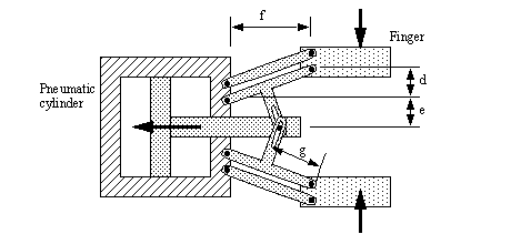
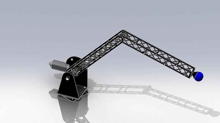
Picking Mechanism: Basic Arm
Design:
In this mechanism we have used a manually controlled robotic arm with 2 degrees of freedom and a gripping mechanism.
Material required :
-
2 DC Motors.
-
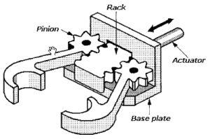
Gripping mechanism (hydraulic gripper,rack and pinion).
-
Rack and pinion mechanism(for the rails).
-
2 elbow joints in perpendicular planes of the arm.
Steps of construction:
-
Connect one motor to the base of the whole arm mechanism. This will help in turning the arm left and right.
-
Connect the other motor to the arm such that its motion causes the ar to move up and down.
Steps of construction: (Gripping mechanism with motors)
-
As shown in figure , keep one side of the part stationary.
-
Attach motor to the end of another part.
-
Make wire connections of the motor such that when the motor is rotated in one direction one part moves towards other part (stationary) and vice versa.
Working:
This mechanism can be divided into two parts-
Mechanical arm
A simple mechanical arm consisting of two motors. The first motor controls the upward and downward movement of the arm. While the second one helps helps in rotating the arm sideways.The arm provides 2 degrees of freedom to move in horizontal as well as vertical direction, so that the arm can reach all the ends of the arena.
Gripper(at the end of the arm)
When the motor is switched on in one direction, the moving part comes close to the fixed part and thus clutches the object in between . When the motor moves in other direction the moving part moves away from the stationary part and thus the object in between is released.
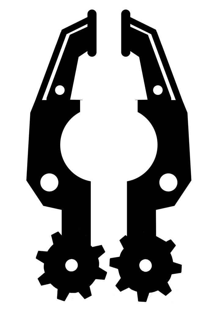
However one can move both the “hands” of the gripper. The movement of one of them is sufficient for carrying out the required task.
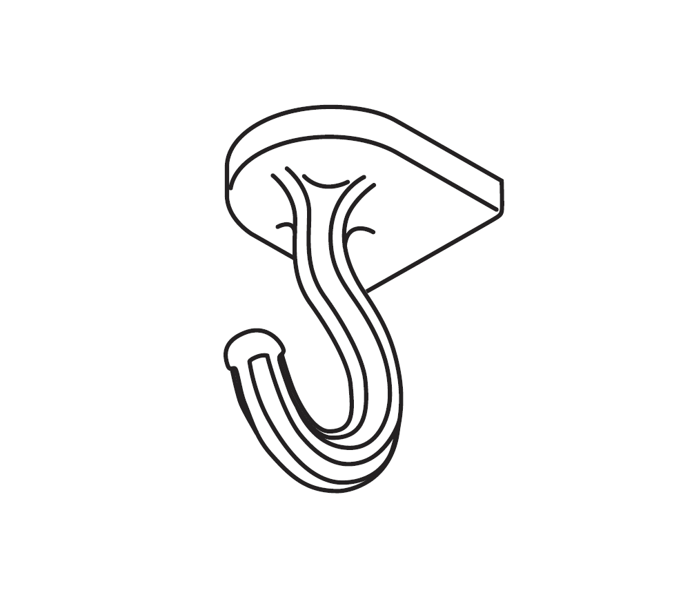
The gripping mechanism is to be used to pick up objects from the pier and place them on the platform. So here we can use a hydraulic gripper, rack and pinion setup or a simple clamp attached to a motor.One may also use hooks for holding the objects with fittings appropriate to it. The grip has to be firm enough to pick up objects and pull loaded carts.