RFID Reader
Radio-Frequency IDentification (RFID) is the wireless use of electromagnetic fields to transfer data, for the purposes of automatically identifying and tracking tags attached to objects. The tags contain electronically stored information.
Readers
RFID systems can be classified by the type of tag and reader.
A Passive Reader Active Tag (PRAT) system has a passive reader which only receives radio signals from active tags (battery operated, transmit only). The reception range of a PRAT system reader can be adjusted from 1–2,000 feet (0–600 m), allowing flexibility in applications such as asset protection and supervision.
An Active Reader Passive Tag (ARPT) system has an active reader, which transmits interrogator signals and also receives authentication replies from passive tags.
An Active Reader Active Tag (ARAT) system uses active tags awoken with an interrogator signal from the active reader. A variation of this system could also use a Battery-Assisted Passive (BAP) tag which acts like a passive tag but has a small battery to power the tag’s return reporting signal.
Active, Semi-passive and Passive RFID Tags:
Active, semi-passive and passive RFID tags are making RFID technology more accessible and prominent in our world. These tags are less expensive to produce, and they can be made small enough to fit on almost any product. Active and semi-passive RFID tags use internal batteries to power their circuits. An active tag also uses its battery to broadcast radio waves to a reader, whereas a semi-passive tag relies on the reader to supply its power for broadcasting. Because these tags contain more hardware than passive RFID tags, they are more expensive. They are reserved for costly items that are read over greater distances – they broadcast high frequencies from 850 to 950 MHz that can be read 100 feet (30.5 meters) or more away. If it is necessary to read the tags from even farther away, additional batteries can boost a tag’s range to over 300 feet (100 meters). Passive RFID tags rely entirely on the reader as their power source. These tags are read up to 20 feet (six meters) away, and they have lower production costs, meaning that they can be applied to less expensive merchandise. These tags are manufactured to be disposable, along with the disposable consumer goods on which they are placed. Whereas a railway car would have an active RFID tag, a bottle of shampoo would have a passive tag.
Storage
Another factor that influences the cost of RFID tags is data storage. There are three storage types:
- read-write
- read-only
- WORM (write once, read many).
Read-write tag’s data can be added to or overwritten. Read-only tags cannot be added to or overwritten – they contain only the data that is stored in them when they were made. WORM tags can have additional data (like another serial number) added once, but they cannot be overwritten.
Advantages:
- No line of sight requirement.
- The tag can stand a harsh environment.
- Long read range.
- Portable database.
- Multiple tag read/write.
- Tracking people, items, and equipment in realtime.
- Can easily be embedded in an object.
RFID Reader: 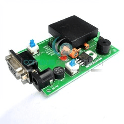
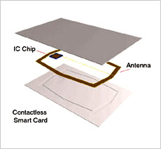
RFID Cards:
outside: 
inside: 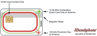
Sample code for RFID detection
/*the following code is to print the RFID value of the card.
we have used the Arduino Mega and put the RFID reader Tx pin in Rx1 */
#include <SoftwareSerial.h>

// The following is the card no. for 3 cards. You will be provided these numbers.
String c1="29003359BBF8";
String c2="29003358A0E2";
String c3="2900336893E1";

String a="";
String s="";
void setup()
{
   Serial.begin(9600);
   Serial1.begin(9600);
}
void loop()
{
  if(Serial1.available())
  a=a+(char)Serial1.read();
  s=a;

  if(s.equalsIgnoreCase(c1))
    Serial.println(s+" p1");
  else if(s.equalsIgnoreCase(c2))
    Serial.println(s+" p2");
  else if(s.equalsIgnoreCase(c3))
    Serial.println(s+" p3");
}
Forklift Mechanism
Introduction:
Forklift is basically a vehicle with a pronged device in front for lifting and carrying heavy loads.
Types of Mechanisms:
Here we are going to discuss these mechanisms of forklift:
- Rack and pinion mechanism
- Hydraulic mechanism
Rack and Pinion Mechanism
AAaQ rack and pinion is a type of linear actuator that comprises a pair of gears which convert rotational motion into linear motion.
Design: 
Material required:
- Rack
- Pinion
- Wooden planks
- DC Motor
- Wires
Working:
- A motor governs the motion of the circular gear(pinion).
- The pinion engages teeth on a linear “gear” bar called “the rack”; rotational motion applied to the pinion causes the rack to move relative to the pinion, thereby translating the rotational motion of the pinion into linear motion.
- When the rotation of the pinion forces the rack to move, the platform, attached to the rack, moves up/down depending on the direction of rotation of pinion.
Hydraulic Mechanism
A rack and pinion is a type of linear actuator that comprises a pair of gears which convert rotational motion into linear motion.
Design: 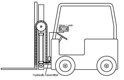
Working:
- When the button is pushed for hydraulic, pressure in liquid spreads throughout, and implements greater force at the transmitter platform.
- Force on platform = Force on button x (Area of button / Area of output nozzle)
- Due to this push, the platform moves down, and hence there is a downward tension in the string of pulley.
- Due to this tension, the forklift rises up.
ACCELEROMETER
As the name suggests, Accelerometer is a device which measures acceleration. Accelerometers are of different sensitivities and ranges. There are accelerometers which measure acceleration in only 2 axes or only 1 axis. Accelerometers with lower ranges such as the ones with 1.5g or 2 g are more sensitive than the ones which have 16 g as their range. The more sensitive accelerometers can be used for measuring tilt whereas the less sensitive ones (such as the one which has range 16 g) can be used to measure shock. For understanding what accelerometer exactly measures and how it works, one must have basic knowledge of vectors and its resultant. In this tutorial, we’ll be working on accelerometer IC called ADXL335. This is MEMS which stands for micro electro-mechanical system. This accelerometer has a 3-dimensional measurement. That means it can measure acceleration along 3 axes. It has a range of +3g with a typical sensitivity of 300mV/g at 3V supply. Refer to its datasheet for more information on sensitivity and zero voltage.
Our world is a 3-dimensional world. So, whatever force of gravity you have can be resolved into 3 components – The X component (Ax), the Y component (Ay) and the Z component (Az). The resultant of these 3 components gives the total amount of force acting. However, it won’t give you the acceleration in m/s2 directly. The output from the accelerometer will be in V which will vary within a certain range as you move it in the possible directions. The voltage obtained is to be multiplied with the sensitivity so as to get the amount of gravitational acceleration acting. In this tutorial, we’ll be observing the variation in the ADC value as we tilt the accelerometer. The more the tilt, more must be the ADC value.
Pin Explanation
Any accelerometer chip has the following pins at least: Pin X: O/P pin which gives voltage corresponding to the acceleration sensed along the X axis. Pin Y: O/P pin which gives voltage corresponding to the acceleration sensed along the Y axis. Pin Z: O/P pin which gives voltage corresponding to the acceleration sensed along the Z axis. Vcc: Supply Voltage Gnd: Ground ST: Stands for self test.
Working
They measure acceleration not by calculating how speed changes over time but by measuring force. How do they do that? Generally speaking, by sensing how much a mass presses on something when a force acts on it.
This is something we’re all very familiar with when we’re in cars. Imagine you’re sitting in the back seat of a car, happily minding your own business, and the driver accelerates suddenly to pass a slow-moving truck. You feel yourself thumping back into the seat. Why? Because the car’s acceleration makes it move forward suddenly. You might think you move backward when a car accelerates forward, but that’s an illusion: really what you experience is the car trying to move off without you and your seat catching you up from behind!
The laws of motion tell us that your body tries to keep going at a steady speed, but the seat is constantly pushing into you with a force and making you accelerate instead. The more the car accelerates, the more force you feel from your seat—and you really can feel it! Your brain and body work together to make a reasonably effective accelerometer: the more force your body experiences, the more acceleration your brain registers from the difference between your body’s movements and those of the car. (And it picks up useful clues from other sensations, including the rate at which moving objects pass by the window, the change in sound of the car’s engine, the noise of the air rushing past, and so on.) Moment by moment, you sense changes in acceleration from changes in sensations on your body, not by calculating how far you’ve traveled and how long it took. And accelerometers work in broadly the same way.
Sample Code for RFID detection
/*the following code is to print the RFID value of the card.
we have used the Arduino Mega and put the RFID reader Tx pin in Rx1 */

//we connect the Accelerometer pin x to A2 and y to A3

void setup()
{
  Serial.begin(9600);
}
void loop()
{
  awx = analogRead(A2);
  awy = analogRead(A3);
}

//Now awx and awy have the analog value corresponding to the orientation of the accelerometer.