TOOLS:
-
Soldering Iron
-
Laptop
-
Visual Studio / MATLAB / Any IDE with an Image Processing Library
-
AVR programming software / Arduino IDE
MATERIALS:
-
2 Wheels
-
1 Castor Wheel
-
Metal Chassis
-
2 DC motors
-
1 Development Board
-
1 Microcontroller (ATmega 16/32/328)
-
1 Programmer (ISP/Arduino)
-
Motor Driver (L293D)
-
1 LED
-
Relimates
PROBLEM STATEMENT:
Build an image processing robot capable of detecting characters, using an overhead camera and traversing them such that the equation generated by the traversal fulfills a certain condition.
We’ll split the Problem Statement into Modules.
In this DIY , we’ll step by step discuss each module. The first thing to do is to make a mobile robot capable of moving according to instructions received from the laptop.
PART 1 - A REMOTE CONTROLLED ROBOT:
LOCOMOTION
The robot can be made to move by using a differential drive as the base. With independent motors for the left and right sides of the base, differential drives allow the robot to move in all directions and turn as well. How the motors will rotate will be determined by the voltage supplied to the motor by the motor driver circuit, which in turn will depend on the instructions sent to the motor driver by the microcontrollers. For more details on differential drives, please check here.
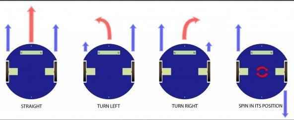
Fig: The schematics of a differential drive
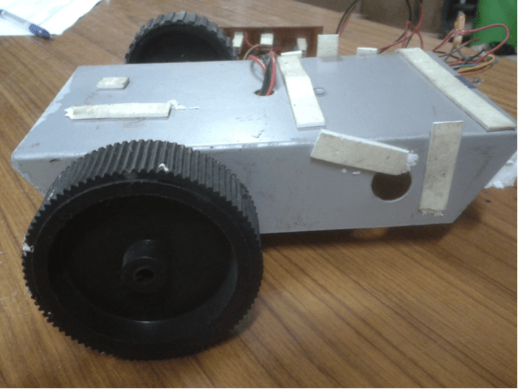
Fig: An actual differential drive
MICROCONTROLLER
Conceived to be the brain of the robot, the microcontroller is the device that allows us to control the robot and make it autonomous. By pre-programming it, we can make it give different outputs based on different inputs and instructions received, and thereby the robot acts accordingly. For a more elaborate understanding of the working of an AVR microcontroller, please visit here. Essentially you only need to program the microcontroller on your robot, to move in a particular direction, based on the character received by it from the laptop.
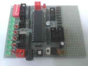
Fig: The development board for the microcontroller from Robokits
The code to be burnt on Arduino is as follows :
char inChar;
int motor_delay = 100;

int LED = 13;
// ---------------------- Motors
int motor_left[] = {4, 5};
int motor_right[] = {2, 3};

// ---------------------- Setup
void setup() {
Serial.begin(9600);
int i;
for(i = 0; i < 2; i++){
	pinMode(motor_left[i], OUTPUT);
	pinMode(motor_right[i], OUTPUT);
	pinMode(LED,OUTPUT);
}

}

// ---------------------- Loop
void loop() {
   if (Serial.available() > 0) {
     inChar = Serial.read();      // get incoming byte:
    switch (inChar) {

      case 'w':
        drive_forward();
        break;

      case 's':
        drive_backward();
        break;

      case 'a':
        turn_left();
        break;

      case 'd':
        turn_right();
        break;

       case 'q':
        full_left();;
        break;

       case 'b':
        motor_stop();
        break;

       case 'e':
        full_right();
        break;

       case 'l':
        digitalWrite(LED,HIGH);
        delay(2000);
        digitalWrite(LED,LOW);
        break;

    }
  }


}

// ---------------------- Drive

void motor_stop(){
	digitalWrite(motor_left[0], LOW);
	digitalWrite(motor_left[1], LOW);
	Serial.println("Stop");
	digitalWrite(motor_right[0], LOW);
	digitalWrite(motor_right[1], LOW);
	delay(25);
}

void drive_forward(){
	digitalWrite(motor_left[0], HIGH);
	digitalWrite(motor_left[1], LOW);
	Serial.println("Forward");
	digitalWrite(motor_right[0], HIGH);
	digitalWrite(motor_right[1], LOW);
}

void drive_backward(){
	digitalWrite(motor_left[0], LOW);
	digitalWrite(motor_left[1], HIGH);
	Serial.println("Backward");
	digitalWrite(motor_right[0], LOW);
	digitalWrite(motor_right[1], HIGH);
}

void turn_left(){
	digitalWrite(motor_left[0], LOW);
	digitalWrite(motor_left[1], LOW);
	Serial.println("Left");
	digitalWrite(motor_right[0], HIGH);
	digitalWrite(motor_right[1], LOW);
}

void turn_right(){
	digitalWrite(motor_left[0], HIGH);
	digitalWrite(motor_left[1], LOW);
	Serial.println("Right");
	digitalWrite(motor_right[0], LOW);
	digitalWrite(motor_right[1], LOW);
}

void full_left(){
	digitalWrite(motor_left[0], LOW);
	digitalWrite(motor_left[1], HIGH);
	Serial.println("Full Left");
	digitalWrite(motor_right[0], HIGH);
	digitalWrite(motor_right[1], LOW);
}

void full_right(){
	digitalWrite(motor_left[0], HIGH);
	digitalWrite(motor_left[1], LOW);
	Serial.println("Full Right");
	digitalWrite(motor_right[0], LOW);
	digitalWrite(motor_right[1], HIGH);
}
PART 2 – COMPUTER VISION
Before proceeding with this module, we would request you to go through the set of general tutorials for computer vision, for both MATLAB and OpenCV, also found on our website. It is quite extensive, and we will assume that a working knowledge, as put forward there, is in the grasp of the reader of this tutorial.
Detecting Contours
We need to first scan the characters present in the arena using an overhead camera. A good approach to solve this problem would be to segment out the characters from the image that is taken by the camera. Use bounding rectangles to take out the portion of the image containing the character. A method called contour detection can be used to figure out the bounding rectangle.
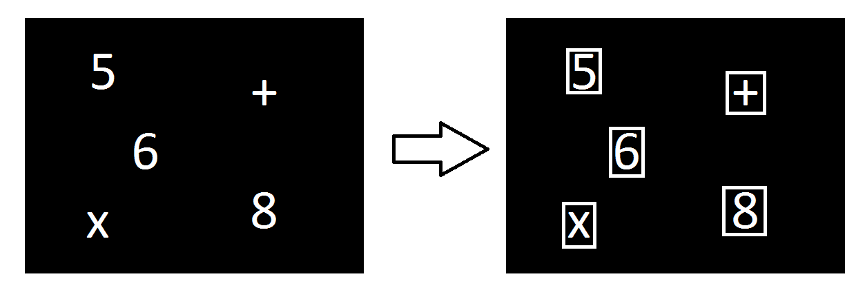
Note that the video feed will contain some noise. Therefore you will not have a perfect image, and hence character detection may become really difficult or you might get wrong predictions. Therefore it is advised to use filters to smoothen your image.
Also note that the contours might not be straight rectangles as viewed by the camera. You should take into account skewed rectangles too.
Predicting Characters Using OCR
Now given that you have n contours where n is the number of characters, you will have to process them so that they return these characters as strings and their positions in the arena. Optical Character Recognition (OCR) is a machine learning problem, which can be solved using a Naive Bayes Classifier. Read more about OCR using OpenCV (an image processing library) in this tutorial. You’re free to train your own classifier to solve the prediction problem. Also usage of OCR libraries is allowed.
Finding a valid expression
Now given that you have all the characters present in the arena.Design an algorithm that would return you a valid mathematical expression.The mathematical expression among these which satisfies the condition stated before the run is your unique expression.Form a que of the characters you need to visit according to this expression.This que would contain the co-ordinates of the characters and the co-ordinates of the end zone to terminate the run.This que would essentially tell the robot its complete route.
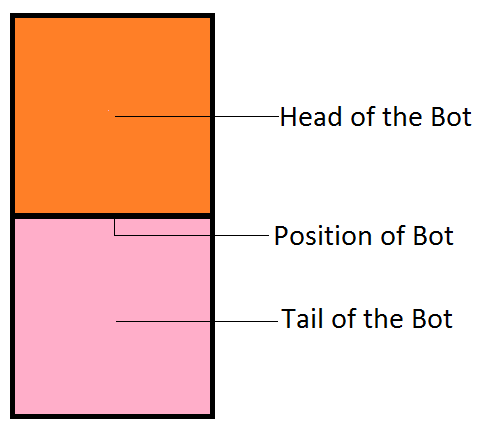
Tracking the Position of the Robot
Throughout your run you will require to track the position of the robot.A marker for the same will be provided.The marker will consist of two squares with different colours.RGB values of the colours will be provided.First we need to scan the input image to get all the points whose colour is roughly the same as the colour of square 1/Head.The centre of all these points is the centre of the Head.Similarly we can find the centre of the Tail.The geometric midpoint of these centre can be fairly estimated as the Position of the Robot.
Locomotion of the Robot
Now that we know the position of the bot and the position of every subsequent character according to the queue we need to send commands to the robot so that it moves to that particular position.Since all the readings are not accurate with the help of overhead camera we just need to move the robot so that its distance with respect to the subsequent position is less than a certain threshold.