Problem Statement
“Build a pair of manually controlled robots that coordinate with each other to rebuild the broken pathway and fill the water puddles.”
Therefore your robot needs to have the following abilities-
-
Water traversing mechanism
-
Differential drive mechanism
-
Robotic arm mechanism
How this Tutorial works
This is a guide for an enthusiast like you to explore your own imagination and incorporate them in your robot for ROBOTIX ‘16 edition.The tutorial lists out all the skills that the event requires your bot to have and tells you exactly how you can implement each of them. And finally, find our ‘Tips’ to put together all your mechanisms and build a winning robot!
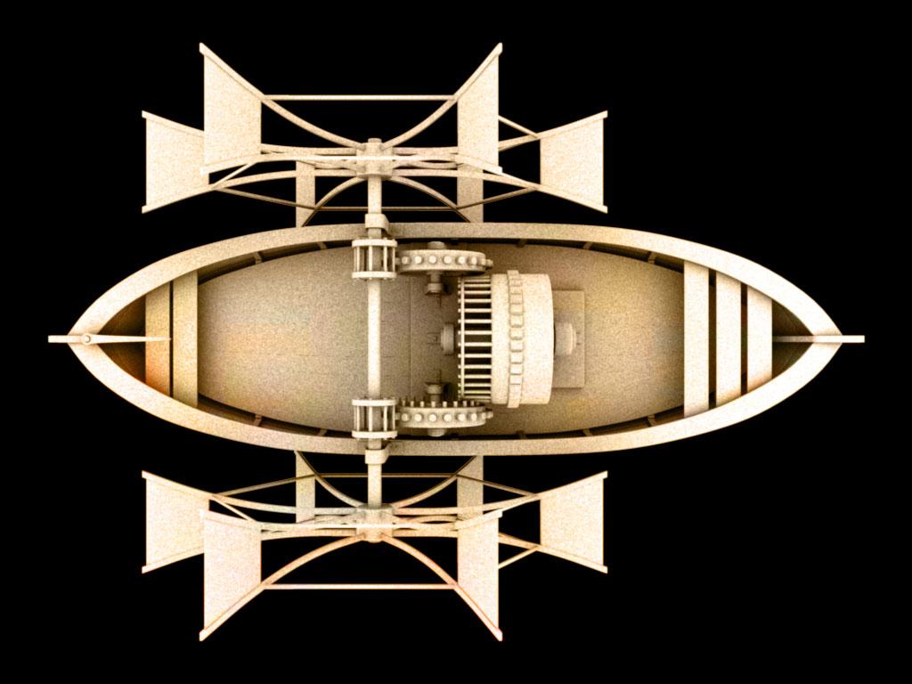
MECHANISM 1 | Water Traversal( Paddle)
Designing a Robot Boat
There are several important things to be considered when building a robot boat. There are weight issues, balance issues, hydrodynamics, waterproofing, the actuator, and sensing problems. There are many different designs that can be made, here is one of them.
Weight
Weight is important when loading the robot boat with various equipment. It needs motors, batteries, sensors, controllers, it all adds up. If the weight is too much, the boat will sink dangerously low - or at least add a lot of drag to its movement. Fortunately, this is an easy calculation to do. First add up the weight of all components for the entire boat, including the hull. Then estimate the desired length and width of your boat hull.
Here is calculation to determine how much the boat will sink under a given weight and hull dimensions:
density x volume = mass
density of water x boat volume under water = boat weight
density of water x length x width x depth = boat weight
sinking depth = boat weight / (density of water x boat length x boat width)
The sinking depth of the boat has to be as minimal as possible, but yet deep enough the actuators can go into the water. If making a robot sub, then the sinking depth has to be equal to the height of the sub, to obtain neutral buoyancy. Density of water is about 62 lbs/foot, and in salt water about 64 lbs/foot.
Actuators
To keep it simple, the paddle wheel is chosen. Unlike propellor driven boats, this type of actuation allows for the use of the most simplest robot control algorithm - differential steering. Propellor driven boats are designed for speed and efficiency, but they don’t perform so well in maneuverability. They also pose significant control algorithm challenges. Even more important, a paddle wheel boat can do 360’s without ever moving forward.
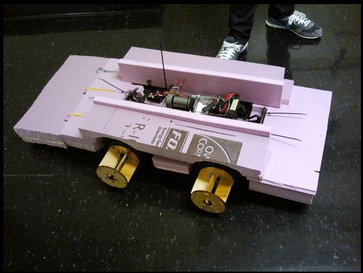
Paddle Construction
The method used here was to take a wooden dowel, bandsaw a slit into it, place pieces of balsa wood into the slit, then superglue the pieces in. The wooden dowel was then press fit into a block of foam core:
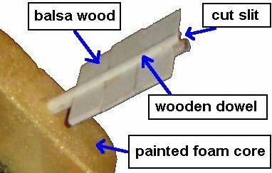
This link shows the paddle mechanism.
MECHANISM 2 | Water Traversal (Propeller)
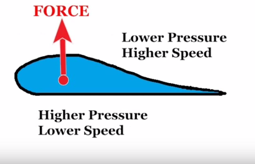
Working Principle:
Basically a propellor is made up of a twisted airfoil-shaped blade.Different regions of blade acquire different speeds due to spinning of the blade.Fluid sections near the centre have lower speed whereas fluid sections near the tip have higher speed because of greater radius.This movement of blade draws fluid.As pressure of the fluid is inversely proportional to speed of the fluid (Bernoulli’s principle).Fluids flow from high pressure to low pressure.By Newton’s third law,there is an equal and opposite reaction to every action.As fluid flows in the backward direction,the boat is pushed to move forward.This is how a propellor works.
Materials needed
-
Two water bottles
-
Two simple dc motors
-
Two propellers
-
Isolating tape
-
Box
-
Battery
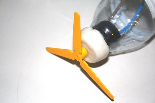
Add the motor and the propeller to each bottle
-
Take out the bottle cap and insert the motor on its mouth (you can use some insulating tape if you see that there is space between the motor and the plastic).
-
Use polymorph to seal the bottle.
-
Attach the propeller.
Connect the two bottles
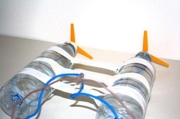
We have used a polymorph extruded tube to pass, give structure and pass the motors’ wires and insulating tape just to support the box.
This video link makes the propellor mechanism easy to understand.
MECHANISM 3| Differential Drive
This is a primer project which covers following concepts -
-
1.Power Supply (Adapter or Rectifier)or 12v battery
-
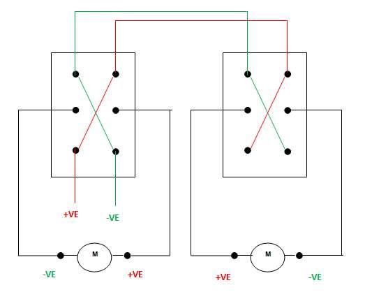
2.Three way switch operation.
-
3.DC Geared Motors
-
4.Basic motion of Robot
Components Required
-
Soldering Iron
-
Soldering Wire
-
Wire Stripper
-
Single strand wires
-
Multi strand wire of appropriate length
-
PCB (dot)(optional if using adapter)
-
4 Diodes (D1N4007)(optional if using adapter)
-
1 Electrolytic Capacitor (1000 microfarad)
-
Step down Transformer (220v- 12V AC)
-
Two 3 way switches or Two 2 way switches and two push button switches.
-
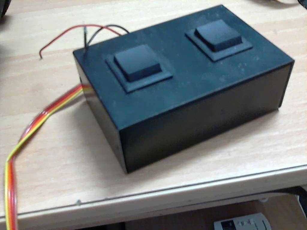
2 plastic boxes to encase transformer and for control box
-
Plug for transformer(optional if using adapter)
-
2 pin, 4 pin relimates
-
Insulation Tape
-
IC 7805(optional if using adapter)
-
DC motors
-
Breadboard (optional)
-
Multimeter
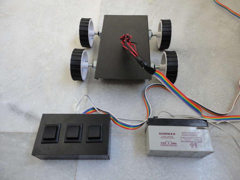
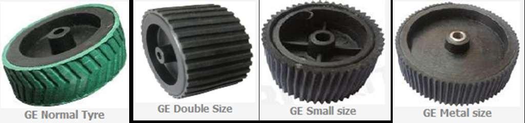
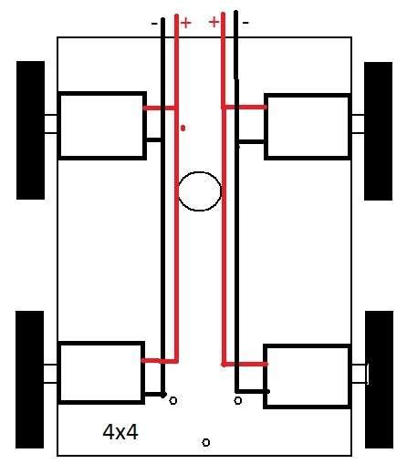
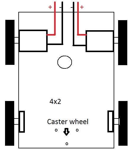
Chassis
Chassis is a mechanical assembly for making a 4 wheel drive platform.Where you can mount any controller board to drive your bot. This is just the mechanical chassis, Optionally as shown in the figure you can use 4 DC geared motors, 1 castor and 4 wheels with rubber rings so you can make both variants .
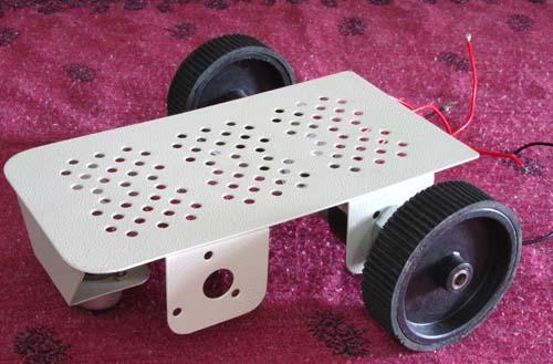
Mechanical Assembly
Fit the caster wheel at position show in above diagram with 1.5-2 inches (approx.) screw. Fit the dc motor into the holes of chassis and couple the wheel by using screw or rubber tube.
This is the circuit design for differential drive.
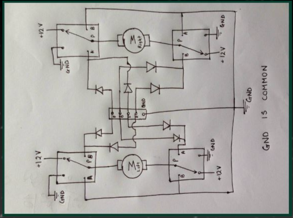
Three way Switch Circuit
Motor Connections
The motors are fixed to the chassis and the tyres are fitted to the DC Geared Motors.
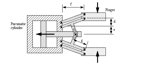
MECHANISM 4 | Robotic Arm
Design:
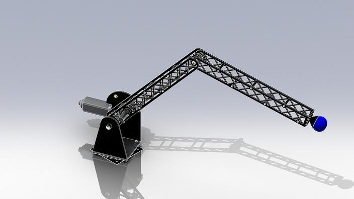
In this mechanism we have used a manually controlled robotic arm with 2 degrees of freedom and a gripping mechanism.
Material required :
-
2 DC Motors.
-
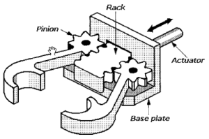
Gripping mechanism (hydraulic gripper,rack and pinion).
-
Rack and pinion mechanism(for the rails).
-
2 elbow joints in perpendicular planes of the arm.
Steps of construction:
-
Connect one motor to the base of the whole arm mechanism. This will help in turning the arm left and right.
-
Connect the other motor to the arm such that its motion causes the ar to move up and down.
Steps of construction: (Gripping mechanism with motors)
-
As shown in figure , keep one side of the part stationary.
-
Attach motor to the end of another part.
-
Make wire connections of the motor such that when the motor is rotated in one direction one part moves towards other part (stationary) and vice versa.
Working:
This mechanism can be divided into two parts-
Mechanical arm
A simple mechanical arm consisting of two motors. The first motor controls the upward and downward movement of the arm. While the second one helps helps in rotating the arm sideways.The arm provides 2 degrees of freedom to move in horizontal as well as vertical direction, so that the arm can reach all the ends of the arena.
Gripper(at the end of the arm)
When the motor is switched on in one direction, the moving part comes close to the fixed part and thus clutches the object in between. When the motor moves in other direction the moving part moves away from the stationary part and thus the object in between is released.
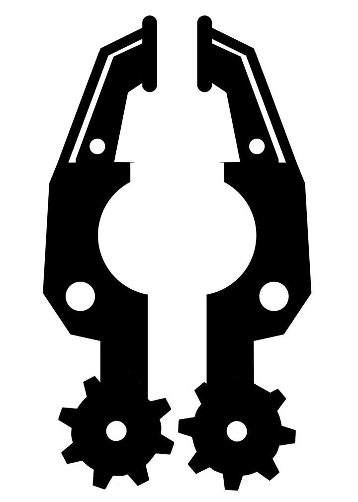
However one can move both the “hands” of the gripper. The movement of one of them is sufficient for carrying out the required task.
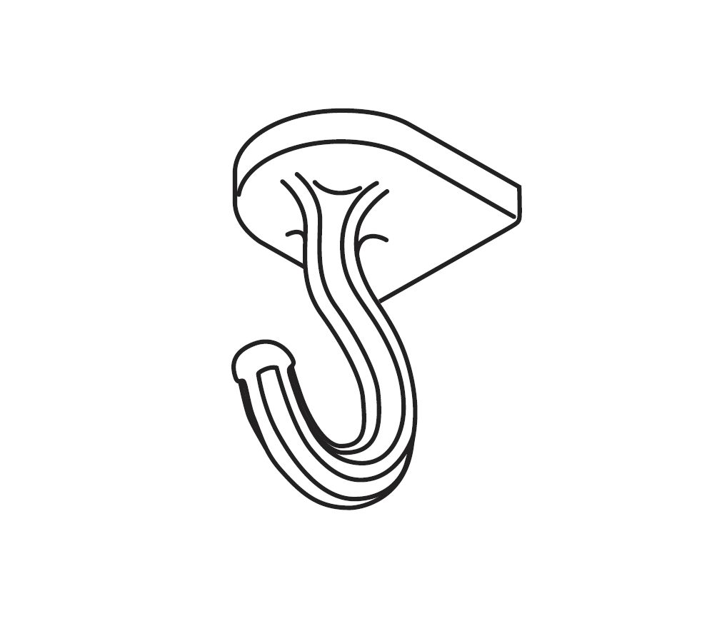
The gripping mechanism is to be used to pick up objects from the pier and place them on the platform. So here we can use a hydraulic gripper, rack and pinion setup or a simple clamp attached to a motor.One may also use hooks for holding the objects with fittings appropriate to it. The grip has to be firm enough to pick up objects and pull loaded carts.
MECHANISM 5 | Amphibious Bot
Design:
This mechanism covers the description of mechanical design of amphibian robot capable of both land and water locomotion driven by motors.
The part where we need to build a robot that can transverse on land is quite easy. But as we need it to float on water, we design the bot in such a way that it is slightly positive buoyant.
ACRYLIC BODY:
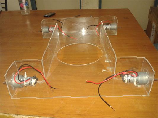
The robot’s body is made of acrylic, as we need to make it positively buoyant, so a light weight material like acrylic, having density of 1.18g/cm3, is best. Acrylic sheet is cut into different parts of the robot using water jet or laser cutter. Each part of the robot has grooves in it, so that each part fits in properly. This provides extra strength to the robot. Acrylic parts are joined together using chloroform, which works as an adhesive for acrylic.
TERRESTRIAL LOCOMOTION:
The Robot moves on land simply with wheels. Four wheels are attached at each corner of the robot. Two wheels at each side move in same direction always. The robot moves in front and back when each pair moves in same side. It turns right when right pair moves in back and left in front direction and vice versa.
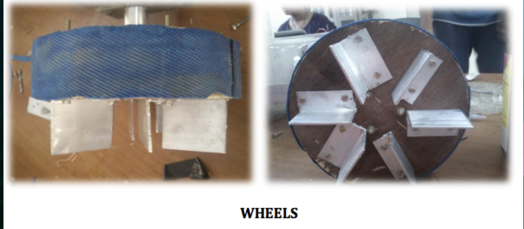
WHEELS:
The wheels are made of wood, having a diameter of 16 cm. Wheels of large radius are needed for better ground clearance, so that bot can travel in rough terrain without damaging any of its parts. The wheels have aluminum angles screwed to it. They help the robot to push water effectively.
AQUATIC LOCOMOTION:
The robot can easily move on water surface with the help of propellers present at its back. To make the robot advance on water surface we need to keep it floating. Thus, the buoyant force should be greater than weight of the body.
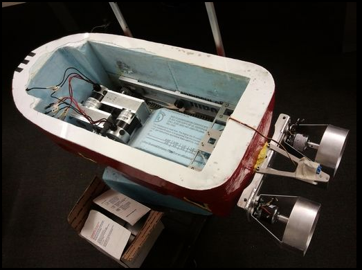
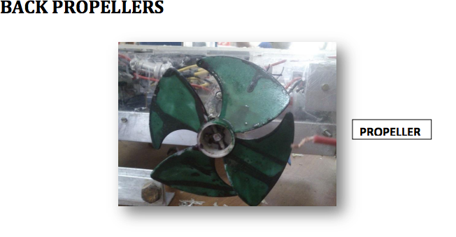
BACK PROPELLERS
There are two propellers present at the rear of the robot, made of plastic and having a diameter of 11cm. They help in locomotion on the water surface. As the ground clearance is small we are not able to use large diameter propellers at back, otherwise they will touch the ground.
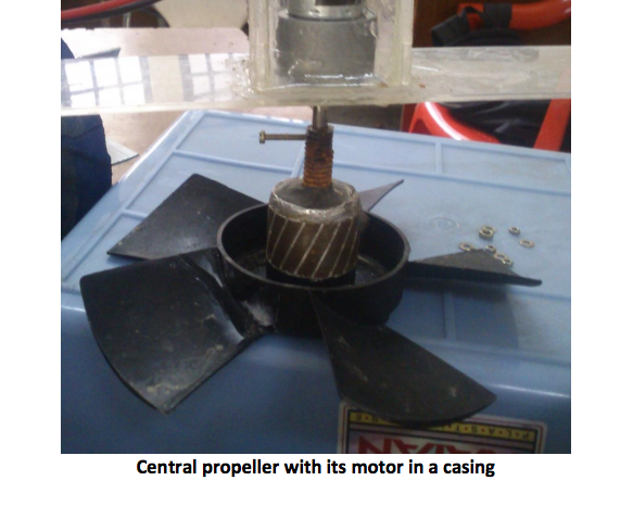
UNDERWATER LOCOMOTION:
Underwater locomotion is achieved by taking the robot inside water using a central propeller. The Aluminium angles attached to the wheels provide enough thrust to change the direction satisfactorily. The central propeller pushes the water upwards which provides a downward thrust to the robot and it goes inside water. The most basic problem with this design is the conservation of angular momentum. As the central propeller rotates, the robot rotates in opposite direction to counter the angular momentum.
CENTRAL PROPELLOR:
Here are certain video links to explain the working further.