Introduction
The atmega16 provides you with two 8-bit timers and one 16-bit timer. Each timer has different modes of operations:
· Normal Mode
· Fast PWM
· Phase Correct PWM
· Clear Timer on Compare Match (CTC) Mode
For the convenience of understanding only Timer0 and Timer2 are covered in this tutorial. Both of these are 8-bit Timers.
How timer works
Since we know that atmega16 is a 8-bit microcontroller. So, everything in atmega16 is controlled by 8-bit registers. The atmega16 keeps the track of time using the TCNTn (Timer/Counter Register, where ‘n’ is either 0 or 2 depending on which timer you are using). In TCNT, each increment corresponds to one Timer Clock Cycle. The Frequency of Timer Clock Cycles is decided by crystal oscillator and the Pre-scaling factor which we can set using the register TCCRn (Timer/Counter Control Register).
Microcontroller has its own frequency of operations (number of operations carried out in 1 sec).
clkIO is the clock frequency of the microcontroller itself (if microcontroller is working on a frequency of 16MHz then the value of clkIO = 16 MHz). By pre-scaling we actually adjust the frequency of counts per second. So, if the pre-scaling factor is chosen to be 64 then the frequency of timer will be 16MHz/64. So, 16000000/64 counts of TCNT will result into 1 second for the above case.
Note: Here, ‘n’ can be only 0 or 2 as Timer0 and Timer2 are 8-bit timers and Timer1 is 16-bit timer. 16-bit Timer is explained in the next tutorial.
Modes of Operation
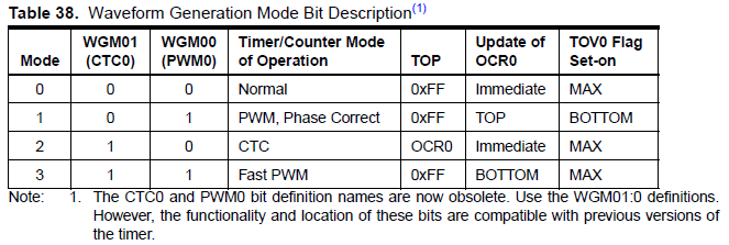
1. Normal Mode :
This is the simplest mode of operation. For 8-bit timer TCNT register starts from BOTTOM (0) and counts till TOP (255). At any point of time you can initialise the value of TCNT according to your wish and note the value of TCNT at other point of time. By this you can measure the time taken by the atmega16 to do the operation.
Example: if you want to measure the time taken by the atmega16 to multiply two 3-digit integers.
PSUDO CODE:
TCNT0 = 0;
unsigned int product = 345*287;//Multiplication of two random 3-digit numbers
unsigned char time = TCNT;//Now time is the number of Timer Clock Cycles
//Multiplying time by the appropriate value of time for each Timer Clock Cycle (in microseconds) we calculate the time taken for the operation in microseconds.
The next three modes require one more topic to be covered and that is PWM(Pulse Width Modulation)
Pulse Width Modulation – PWM :
As the name suggest we can get a hint that there is a Pulse which is generated here. To understand this concept I will consider a Pulse a square wave of voltage vs time.
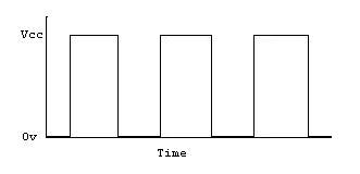
Now what does Width Modulation mean. It means adjusting the time for which the source voltage will be HIGH and the time for which the source Voltage will be LOW.
We can control the Width Modulation by using the two properties of this Pulse
· Frequency
· Duty Cycle
Frequency :
The frequency is the time period of the Square Wave. Time period correspond to the time for one voltage cycle(HIGH to HIGH). If we half the frequency, the time period of one oscillation becomes doubled. So, you can see that is the graph when we adjust the frequency the width of the oscillation can be adjusted.
Duty Cycle :
Duty Cycle is the percentage of time in a time period for which the Voltage is HIGH. The pulse given in the figure suggests that for half of the time the Voltage is HIGH and for the Rest half the Voltage is LOW. So, the duty cycle of the Pulse in the given diagram is 50%.
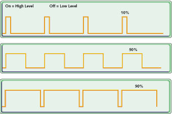
In the Above diagram we can see that by adjusting Duty Cycle we can control the Width Modulation
So, this was the explanation of Pulse Width Modulation in short. Now continuing with modes of operation.
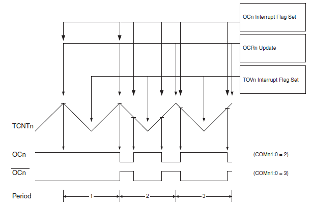
2. Clear Timer on Compare Match Mode(CTC) :
In this mode you can set the value of the TOP. So if you set the value of TOP as 100 instead of 255(default TOP value), the TCNT counts from BOTTOM (0) to 100 and then again drops to BOTTOM (0). So, if the counts of TCNT decrease then the time period of the oscillation decreases. So, in this mode we can adjust the frequency of the. For Adjusting the TOP value in this case we use the OCRn (Output Compare Register). In this mode the OCn pin(for 8-bit timers, OC0 and OC2) is the output pin for PWM.
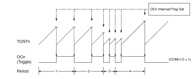
3. FAST PWM Mode :
In this mode the OCn pin(for 8-bit timers, OC0 and OC2) is the output pin for PWM of duty-cycle dependent on the value of OCRn register. The TCNT value goes from BOTTOM(0) to TOP(255). When the value of TCNT matches with that of the OCR register, the OC pin can be reset/set according to the mode selected (non-inverting/ inverting). The diagram for How Fast PWM works is given below
Example : If you want the output PWM to be of 25% PWM then the TCNT should count from 0 to 63(256/4). So we will initialise the value of OCRn to 63. Now, for non-inverting mode, TCNT starts counting from 0. When value of TCNTn is less than OCRn the Output is HIGH at OCn pin and when TCNTn becomes greater than OCRn value then the Output is LOW at OCn pin. When TCNTn overflows(When there is a transition from MAX to BOTTOM) , the output again becomes HIGH and the cycle continues. So, we can see that for the above case the outut of OCn for one time period remains HIGH for only 1/4th of the time period. So, the duty cycle for the above case is 25%.
4. Phase Correct PWM :
In this mode the TCNT increases from BOTTOM to MAX and then falls from MAX to BOTTOM. So in this case the duty cycle will remain same as that in the case of the Fast PWM but frequency is halved.
TCCR Registers
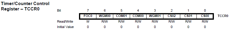
This bit is not required .So we will set it to 0.
Bit 6,3 - WGM01:0: Wave form Generation Mode
These two bits will decide the mode of Timer according to the table shown below
Bit 5,4 - COM01:0: Compare Match Output Mode :
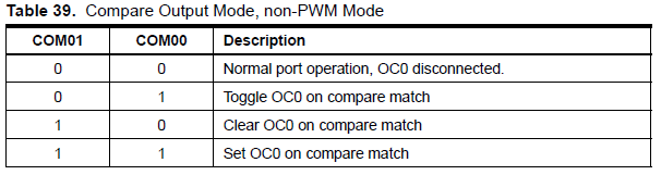
Table 39 shows the COM01:0 bit functionality when the WGM01:0 bits are set to a
normal or CTC mode (non-PWM).
· In first case only timer will be generated and no PWM output will be generated at the OCn pin
· In second case for one time period the OCn pin will be HIGH and for the succeeding time period the value of OCn pin will be LOW.
Clear means setting the Output to LOW
Set means setting the Output to HIGH
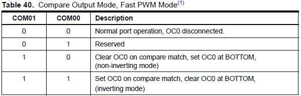
Table 40 shows the COM01:0 bit functionality when the WGM01:0 bits are set to fast PWM mode.
· In first case no Output will be generated on OCn pin
· Second case is reserved. It will not serve our purpose
· Third case will generate a PWM of duty cycle depending upon the value of OCRn and in non-inverting mode
· Fourth case will generate a PWM of duty cycle depending upon the value of OCRn and in inverting mode
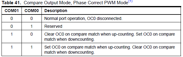
Table 41 shows the COM01:0 bit functionality when the WGM01:0 bits are set to phase correct PWM mode.
· In first case no Output will be generated on OCn pin
· Second case is reserved. It will not serve our purpose
· Third case will generate a PWM of duty cycle depending upon the value of OCRn and in non-inverting mode
· Fourth case will generate a PWM of duty cycle depending upon the value of OCRn and in inverting mode
· Bit 2:0 – CS02:0: Clock Select
Microcontroller has its own frequency of operations (number of operations carried out in 1 sec).
clkIO is the clock frequency of the microcontroller itself (if microcontroller is working on a frequency of 16MHz then the value of clkIO = 16 MHz). By pre-scaling we actually adjust the frequency of counts per second. So, if the pre-scaling factor is chosen to be 64 then the frequency of timer will be 16MHz/64.
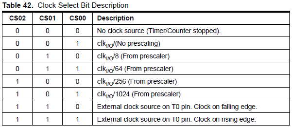
Table 42 shows the prescaling factor for the different values of bits CS02:0