Minefield Tutorial
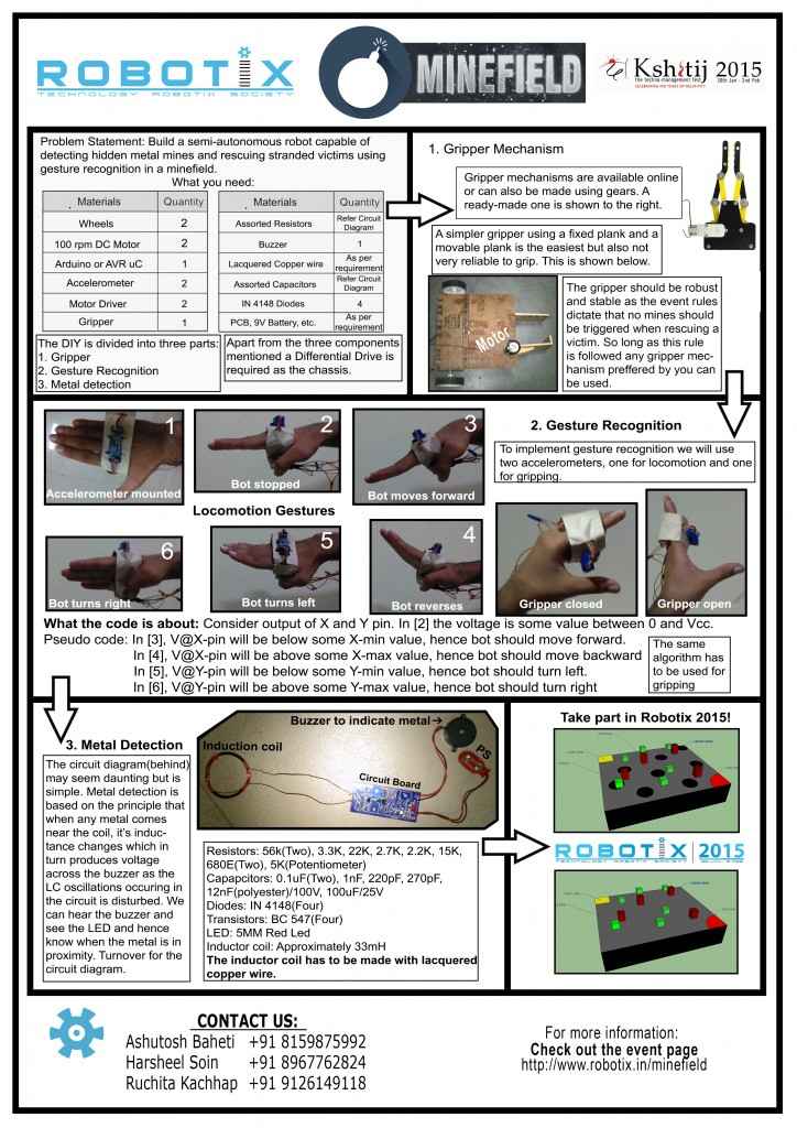
Problem statement: Build a semi-autonomous robot capable of detecting hidden metal mines autonomously and rescuing stranded victims using gesture recognition in a minefield.
Video Tutorial for robot
Introduction:
This tutorial assumes basic prerequisite knowledge of differential drive and microcontrollers. Otherwise, the following tutorials can be referred:
What the robot requires to do?
- Traverse arena using hand gestures.
- Pick and drop victims.
- Identify metal mines on the arena.
Technically what the bot has to do:
- Control the rotation of motors using hand gestures.
- Controlling the gripper using gesture.
- Implement metal detection.
Now let us analyse how each of these can be achieved.
Gesture control: There are many ways by which we can implement gesture control. For that we require a sensor or a device that could differentiate different orientations of our hands with respect to a reference position. we can achieve this by using following sensors and devices.
- Accelerometers
- Gyroscopic sensors/inertial measurement units
- Using camera and image processing.
Let’s have a look at how the methods mentioned above can be employed to achieve our objective - gesture recognition.
We can use a camera that will capture the image of our hand and process the image in order to recognize what orientation it is in and can instruct the bot to move accordingly. But this requires too much of coding and processing power. If you are interested you can go through the image processing tutorials on our website.
Another easier way to achieve gesture control is using sensors like accelerometer or gyroscope sensor. These sensors can be placed on our hand and as we change the orientation of our hand the orientation of the sensors is also changed with respect to a particular reference orientation. Accelerometer or gyroscope sensor?
Both of the above mentioned sensors can be used effectively to achieve what we want, but we would suggest using an accelerometer as is it a lot less expensive than gyroscopic sensors or inertial measurement units and works well, with good resolution.
Moreover gyroscopic sensors calculate angular velocity instead of acceleration so we will have to integrate it in order to get acceleration which can induce more error in the readings.
Gesture control using accelerometer:
Using gesture control we need to accomplish two things:
- Locomotion/traversal
- Clasping victims/objects
In order to understand how an accelerometer works and get an insight into how it can be used to fulfill our purpose, you might want to first go through the accelerometer tutorial on our website and read it thoroughly.
Locomotion/traversal:
After reading the accelerometer tutorial, you will get an idea about how an accelerometer works, and can then work on the following set of instructions:
Let the accelerometer be placed on the top of the palm with the palm parallel to the ground. Consider the x axis output values of the accelerometer. Here X axis is along your hand as indicated by the horizontal dashed line in the following images. The ADC values of x-out pin in accelerometer will vary from one extreme to another extreme corresponding to the following two extreme positions of the palm (i.e. forward tilt and backward tilt) and would lie somewhere in between the two when the palm is parallel to the ground. -Say the ADC values from the output pin “x-out” vary from 100 to 450 between the extremes and is around 250 in the middle.
 Fig 1 : One extreme(adc value is minimum, say 100)

Fig 2 : Other extreme(adc value is maximum, say 450)
Similarly, along the y-axis let the values of the “y-out” pin vary from 100 to 450 during left extreme tilt to right extreme tilt respectively. The y-axis is as shown in the figure, perpendicular to the x-axis, in the plane parallel to the ground.

Fig 3: One extreme(“y-out” adc value is minimum, say 100)

Fig 4: One extreme(“y-out” adc value is maximum, say 450)
Algorithm for controlling the motors: Now that we have different ranges of ADC values for each gesture, we can run our Differential drive according to it depending on which range the ADC values of the 3 output pins is lying.
Pseudo Code:
//Comment this code or replace the numeric values with X-min (value of X-axis when hand bent down), X-max (value of X-axis when hand bent up), X-mid (Middle range)
if(x-out<125 && y-out >125 && y-out<425) // move forward;
else if(x-out>425 && y-out >125 && y-out<425) // move back ;
else if(x-out>125 && x-out <425 && y-out>425) // move right;
else if(x-out<125 && x-out >425 && y-out<125) // move left; else stall;
Clasping victims/objects:
Clasping of objects can be done in a similar way using another accelerometer using the ADC values of any one of the axis. we used a servo operated gripper for gripping the objects. Let the accelerometer be placed on the inside ot the palm being perpendicular to the ground as shown.

Fig: Orientation 1
 Fig: Orientation 2
Let the ADC values of the reference axis pins be 50-150 (For Orientation 1) and 300-400(For Orientation 2). Now a simple code can be used to operate the gripper corresponding to the values of the the output pin of the reference axis.
Pseudo Code:
if (out>50 && out<150) servo position X Deg; //position of servo corresponding to gripper open else if (out>300 && out<400) servo position Y deg; //position of servo corresponding to gripper closed
Metal Detection:
A more interesting and challenging part of this event is mine detection, which is analogous to metal detection. There are two main techniques for metal detection-
- Beat-frequency oscillation (BFO)
- Very low frequency (VLF)
- Pulse induction (PI)
For getting an insight into how these methods work you can visit this link.
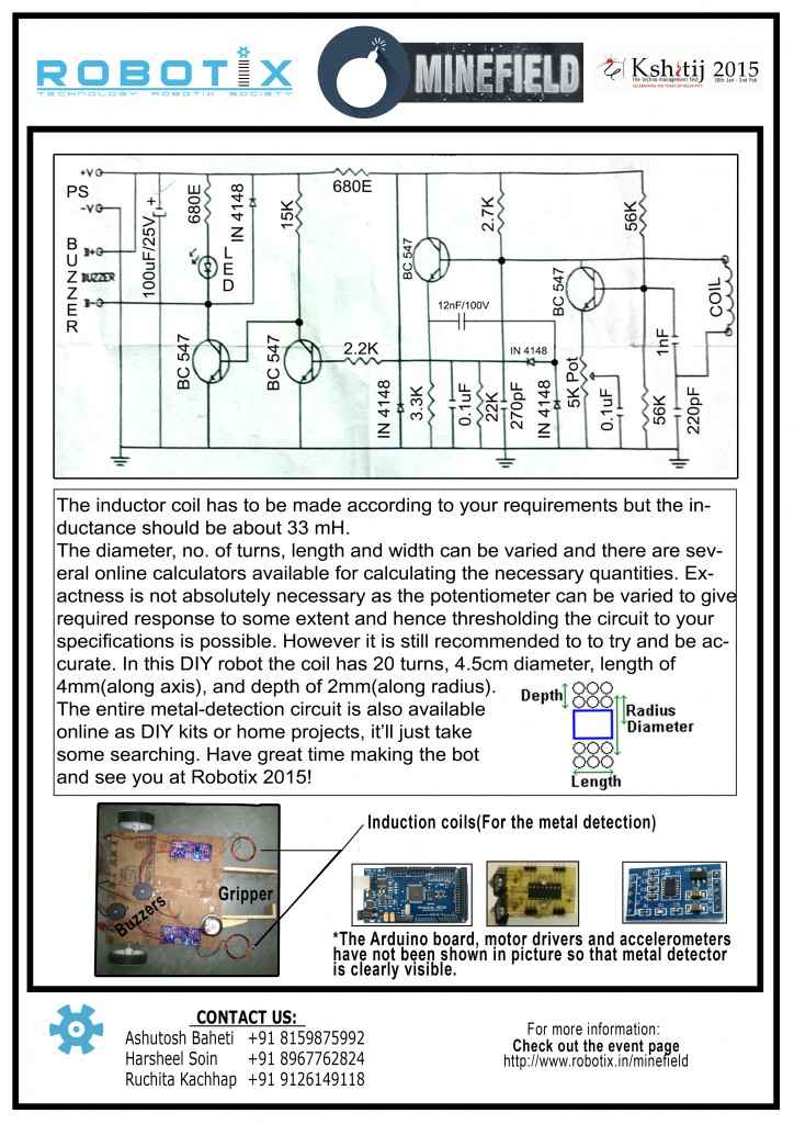
For our testing we used a BFO metal detector. CIRCUIT DIAGRAM:
COMPONENTS:
Here is the Event Video Tutorial.
Event Details can be found here. Tutorial can also be found here. Pictorial Do It Yourself Tutorial (DIY) is here. Facebook Discussion Group for any doubts and queries is here. Register now for the event here.

